How Does a Float Switch Work?

A float switch works to detect the level of liquid in a tank by using a float, magnet, and reed switch system that automatically opens and closes when water levels rise and fall inside the tank.
According to WikiPedia, “A float switch is a type of level sensor, a device used to detect the level of liquid within a tank… One pattern uses a reed switch mounted in a tube; a float, containing a magnet, surrounds the tube and is guided by it. When the float raises the magnet to the reed switch, it closes”.
Basically, float switch systems work by opening and closing dry contacts. Once the dry contacts are opened or closed, they will send an electrical signal to set off a water level alarm. The water level alarm is used to tell the control panel whether the water level is too low or high. If you have an automatic water level control system, the control panel will tell the pump to turn on or off automatically to begin refilling or emptying the water.
How New Float Switches Work
Never replace another float switch or water level controller again with 99% uptime over 15 years. Water Line Controls is the leader in float switch and water level control technology.
Water Line Control’s revolutionary Float switches work by using stainless steel probes (instead of float switches) to detect and sense water levels in a tank (water, oil, gas, etc).
The sensor probes act as their own sensors and do not pass electricity through the stainless-steel probes which keeps them from fouling, degrading, and deteriorating.
All the electronics for the controller are built into the head of the unit so you can connect directly to your control panel. Once the water level is detected by one of the sensors, this causes one of six alarms to be triggered (Low Alarm, High Alarm, Fill Start, Fill Stop, etc.). Depending on the type of water level control system you have, it can be set up to trigger a single point alarm or multi-point alarm.
Different alarms control the different start and stop mechanisms. For example, if a low alarm was triggered in a water tank, that alarm could do one of 2 things (or both in some setups).
- In a single point float switch, a low alarm will trigger an LED light on your control board
- In a multi-point float switch, a low alarm will trigger the LED light to turn on, and also send a signal to automatically turn on or off a water pump to refill or empty the water back to the preprogrammed water level.
Float switches and water level controls usually start out closed, meaning there are no alarms that need to be triggered because the water level is at the predetermined height.
New Float Switch Working Principle
- The water level starts to drop. No alarms are triggered at this point.
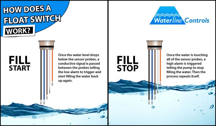
- Once the water level drops below the sensor probes, a conductive signal is passed between the probes telling the low alarm to trigger.
- Once the low alarm is triggered, it can be programmed to tell the “fill start” to begin filling the water.
- Finally, once the water reaches the predetermined height, the “fill stop” kicks in, and the process starts all over again.
With proper maintenance, your float switches/water level controls can last for years of operation. Most float switch failures usually happen due to fouling, degrading, or deteriorating in poor water conditions. Our water level controls can replace your float switches for good and will never foul, deteriorate or degrade due to any water quality.
Why Choose Water Line Controls
All of our water level controls and water level control systems are assembled right here in the U.S.A. where we monitor every step of the process. The are many reasons to choose Waterline Controls™ for all of your float switch and water level controller needs include:
SIMPLE DESIGN
No moving parts or mechanical floats to break or rust!
BEST TECH SUPPORT
No runaround, no guessing, no stupid answers. You’ll talk to the guy who’s been designing and installing these units for over 20 years.
BUILT TO LAST
Makes it easy to integrate with existing Building Management Systems and has an expected useful life of 15 years.
TOUCH TO TEST
One push of the button starts a complete validation cycle to ensure all systems are working properly.
RELIABLE & ACCURATE
Will not foul, plate, or deteriorate regardless of water quality.